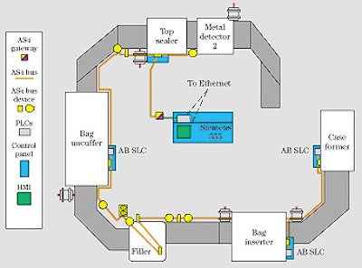
Drawn by Ocean Spray’s Dave Frenz with an assist from Paintshop Pro software, this diagram illustrates how controls are integrated on the new Craisins line. The yellow line represents the two-wire AS-i cable. Connected to every piece of equipment in the line, it permits the central PLC to perform machine-to-machine communications, or interlocks.
Blue rectangles represent PLCs. The three machine-mounted PLCs are Allen-Bradley models from Rockwell, while the central PLC is from Siemens.
Orange rectangles represent control panels. The control panel holding the Siemens PLC is drawn large to represent this PLC’s role as chief “traffic cop” for the entire line. This PLC’s ability to communicate along the AS-i bus is made possible by an “AS-i Gateway” module illustrated as a yellow/magenta square. Also in each control panel is a small yellow rectangle representing an AS-i I/O block. This permits the Siemens PLC to exchange signals with each machine-mounted PLC.
The Siemens PLC acts as a Supervisory Controls and Data Acquisition (SCADA) system, meaning it controls the line and collects real-time data such as cases/min, faults, weighing accuracies, etc. The green rectangle in the Siemens control panel represents the Human-Machine Interface (HMI) that operators use, in this case Wonderware (Irvine, CA) software, to control the line. Also shown is the Ethernet network link, which makes real-time data acquisition possible between the Siemens PLC and the Wonderware-enabled HMI.
Finally, the six yellow circles scattered throughout the line are all photoeyes that Frenz clamped onto the AS-i cable shortly after the installation was complete.These provide added input in places where it was deemed necessary.
See the main story that goes with this sidebar: Ocean Spray rides a new bus