PFM Integrators addressed this challenge by developing a vision application in which a robot passes one bag every second in front of two Cognex DS1100 3D vision systems placed opposite to one another. The vision systems accurately measure the surface profile of each bag. These measurements are used to determine the thickness of the seal and identify any thickness variations that may indicate a failure in the integrity of the seal, such as contaminants stuck in the seal, for example. This application has helped the food processing company increase the safety of its products while reducing labor expenses by reducing the need for manual inspection.
Some food processors have experimented with conventional 2D machine vision to inspect the seals. “When this particular food processor tried inspecting the seals with 2D machine vision, the vision system either rejected every bag or let every bag pass depending on how the vision system was calibrated,” says Ken Baych, President of PFM Integrators. “The problem was that the contaminants trapped in the seal did not provide a sufficient visual signature to be detected by 2D vision systems. A couple of years ago we evaluated the use of 3D vision systems to inspect the seals but at that time the cost of 3D vision systems was so high that we felt they would not be able to provide a sufficient return on investment.”
Over the last few years a new generation of 3D vision systems has appeared on the scene that uses laser triangulation to extract 3D information from parts at a considerably lower cost than the 3D vision systems available in the past. “The vision systems used in this application cost only about one-half of the amount of those that we evaluated in the past,” Baych said. The new 3D vision systems use a laser range finder to project a beam onto the object to be measured. The image sensor captures a three dimensional point cloud of data to calculate the points of the object. This point cloud of data can be used to measure 3D and 2D features such as length, width, height, tilt, or volume. It can be used to detect defects, or presence or absence of features, or raised or embossed characters against a low-contrast background.
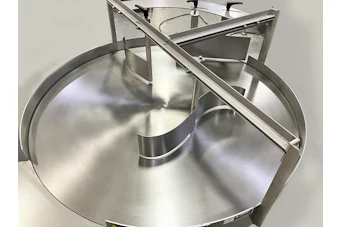
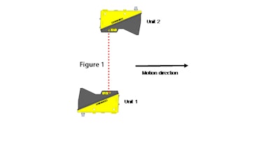
In this application at the unnamed food company, PFM engineers mounted the two vision systems above a linear table that moves horizontally. The X, Y, and Z axes were referenced to a high accuracy calibration block on the table. The X axis is approximately along the laser line, the Y axis is approximately normal to the plane of the laser fan, and the Z axis is in the depth measurement direction. The vision systems are mounted sideways so that the X axis is vertical and the Z axis is horizontal at a right angle to the motion direction. Unit 1 is set up so that the Y axis is aligned with the motion direction. Unit 2 is set up so that the X axis is parallel to the unit 1 X axis, and the Y and Z axes are antiparallel to the unit 1 Y and Z axes. The X and Y origins are roughly aligned, and the Z separation creates a common working section of the required size and shape.
The units are spaced about 480 mm apart at the laser windows. The Z origin of each vision system is 350 mm from the reference pin and the bottom of the working section is 315 mm from the reference pin. Approximately the bottom 110 mm of the working sections of the two units overlaps. The two units were mounted with centerline approximately 100 mm above the table. The height of the overlapped working section is about 120 mm in the center and 80 mm at the near and far ends.
The acquire direction is set up in the lens-to-laser direction for unit 1 and the laser-to-lens direction for unit 2. The acquisition is done with both units set to acquire lens-to-laser, even though unit 2 is actually oriented the other way. This means that the unit 2 image is mirrored and can be matched against the unit 1 image with just the proper translation. The vision systems calibrate themselves by simultaneously capturing an image of the calibration block. Each camera mounted acquires several images of the calibration block and between taking each picture the table moves a known distance. Based on these four images, the calibration routine determines the position of the each camera in relation to the calibration block.
A critical step in setting up the application was distinguishing between good and bad seals. The seal is about 0.25 mm thick as measured by mechanical calipers in the areas where it has a uniform appearance with crosshatch texture on one side. All seals have small voids and lumps that don’t compromise the seal integrity. The voids are typically less than 0.1 mm deep and the lumps are less than 0.2 mm high. Some seals have areas with a melted looking appearance where the crosshatch texture is degraded or missing, but these also do not compromise the seal. Some of these areas are islands within the seal area and the seal also tends to look like this near the edges, especially near the edge where the seal meets the bag interior. Bubbles, wrinkles, or foreign objects trapped in the seal that do not affect airtightness are a cosmetic issue. Some of these are considered defects and some or not, depending on their size and other characteristics.
The 3D vision inspection system provides near 100% accuracy in distinguishing good from bad seals and can be programmed to classify any particular category of seal, such as the ones shown above, as either good or bad. PFM is using this patent-pending technology to develop an inspection system product which can be integrated into most packaging lines. A key advantage of this approach is that it does not require accurate positioning of the bag, which is difficult to accomplish in any event. With the vision systems measuring the profile of each side of the bag in space, accurate thickness measurements are provided even if the bag is in motion at the time the image is acquired. The vision systems also upload each acquired image to a central storage system that can be accessed by manufacturing engineers to rapidly improve the process.